
Introduction — why a structured framework is necessary
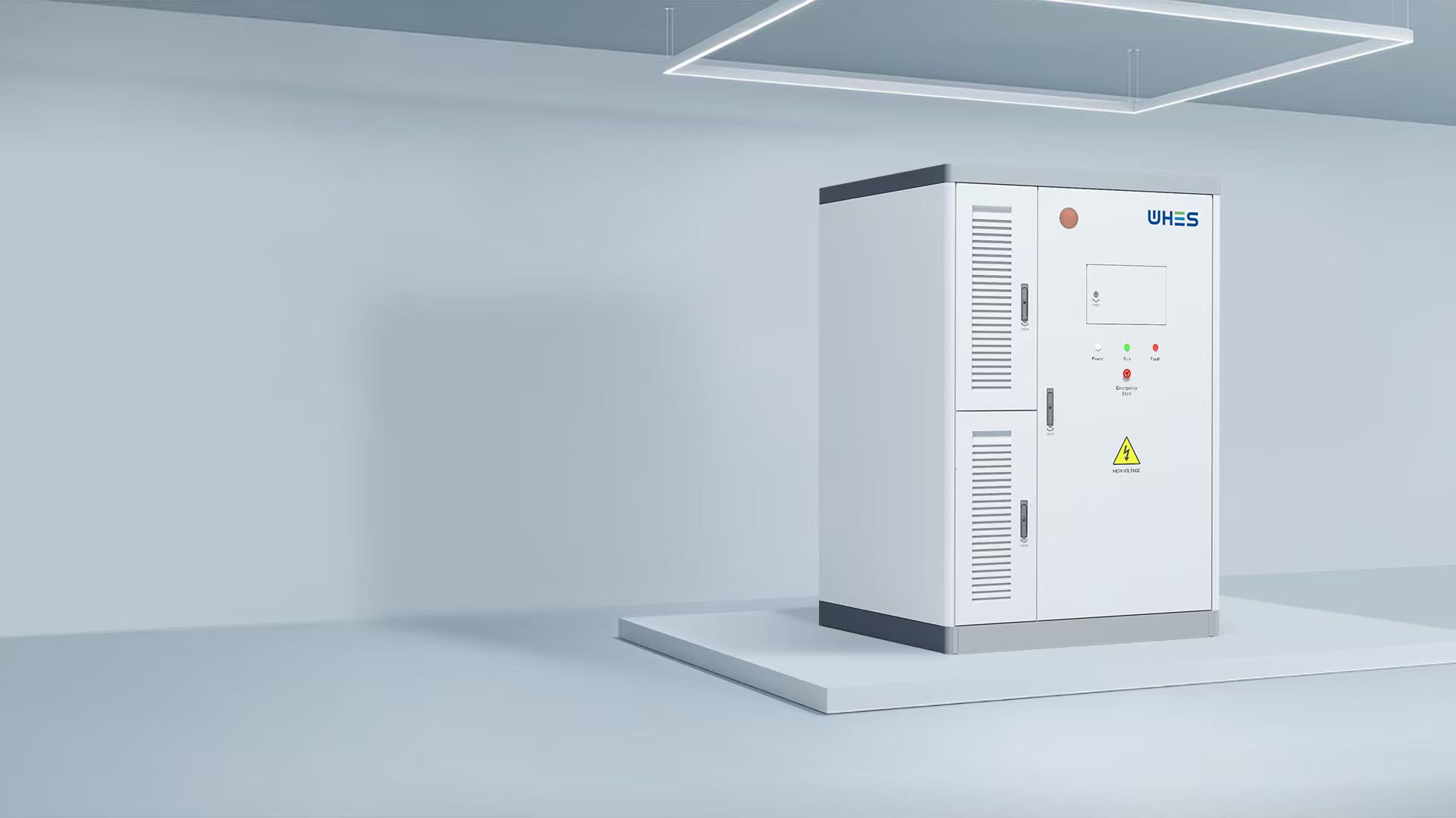
As an energy engineer advising project teams from rooftop microgrids to commercial installations, I find that ambiguity in specification is the most common root cause of operational shortfalls. A deliberately ordered framework prevents that. This guide sets out the engineering logic needed to specify an ESS correctly, with emphasis on round-trip efficiency (RTE) and thermal stability — and it refers where appropriate to integrated hardware such as an all in one energy storage system that reduces interface risk and simplifies commissioning.
Framework overview: objectives, constraints, and use cases
Begin by defining three things: the functional objective (arbitrage, peak shaving, back-up, or grid services), the operating constraints (ambient temperature range, site ventilation, maintenance cadence), and the lifecycle target (10, 15, or 20 years). These items drive choices for rated capacity, cycle life, and the scope of the battery management system (BMS). For example, a commercial load-shifting project prioritises high usable energy and RTE; a resiliency-focused deployment may instead prioritise thermal robustness and proven cell chemistry.
Core technical parameters to specify
Focus specifications on measurable parameters rather than marketing claims. Key values include: rated round-trip efficiency (expressed as a percentage), usable capacity at defined depth of discharge (DoD), sustained operating temperature range, and BMS protections such as cell-level monitoring and thermal cutouts. RTE determines how much energy returns to the system over a full charge–discharge cycle; DoD and cycle life together set the expected energy throughput over the warranty period. Specify these parameters at the cell, module, and system levels to avoid misaligned expectations between suppliers and integrators.
Thermal management: why it changes everything
Thermal stability is not merely a safety checkbox — it affects degradation rate, available power, and long-term cost. A well-designed thermal management strategy reduces the risk of thermal runaway and slows capacity fade. Consider forced-air cooling, liquid cooling, or passive thermal design depending on ambient extremes and site density. In hot climates, derating curves (power or capacity reduction at elevated temperatures) must be explicit in the datasheet so the operator can model worst-case performance and plan ventilation or cooling accordingly.
Testing and acceptance: what to demand in contract language
Insist on factory acceptance testing with the exact control strategy you will deploy, and require transit-shock and thermal-cycling reports. Include performance guarantees for RTE measured under standardised conditions (e.g., specific C-rate, SoC window, and temperature). Define first‑article acceptance tests that include a short-duration power test, a full charge–discharge cycle to verify usable capacity, and simulated fault conditions for BMS response. Where possible, require independent lab verification of cycle-life claims.
Operational trade-offs: efficiency versus thermal margin
Higher nominal RTE often comes with tighter thermal operating envelopes; conversely, systems designed for wide-temperature tolerance may accept slightly lower peak efficiency to avoid overheating during stress events. In many field cases — such as the Hornsdale Power Reserve in South Australia, which demonstrated the value of rapid-response storage at grid scale — operators choose a balance that preserves performance under real transient conditions rather than chasing a headline efficiency number. Model both steady-state efficiency and transient thermal response for representative duty cycles before final selection.
Integration and controls: BMS, inverter pairing, and system-level view
The BMS must enforce the operational limits you specify: cell balancing algorithms, charge cut-offs, and thermal alarms. Equally important is the interface to the inverter — control latency, state-of-charge reporting, and fault propagation paths must be clear. For commercial deployments, consider specifying the communications stack (Modbus, CAN, or Ethernet), and require interoperability testing with your preferred inverter and site EMS so that energy scheduling and islanding behave predictably.
Common specification mistakes and how to avoid them
Frequent errors include over-reliance on advertised peak RTE without context; underspecifying temperature derate behaviour; and omitting real acceptance tests with production firmware. Avoid these by: 1) asking suppliers for RTE measured at the operational C-rate and temperature you expect; 2) requiring explicit derating curves; and 3) making commissioning conditional on performance verification under live conditions. Small omissions at the contract stage compound quickly during commissioning — a point I have seen repeatedly in commercial projects across the Middle East and Europe.
Where all-in-one and turnkey products fit in the landscape
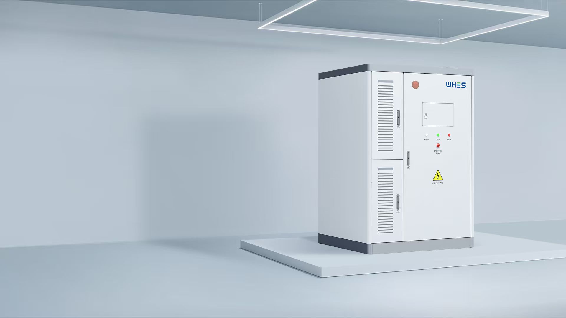
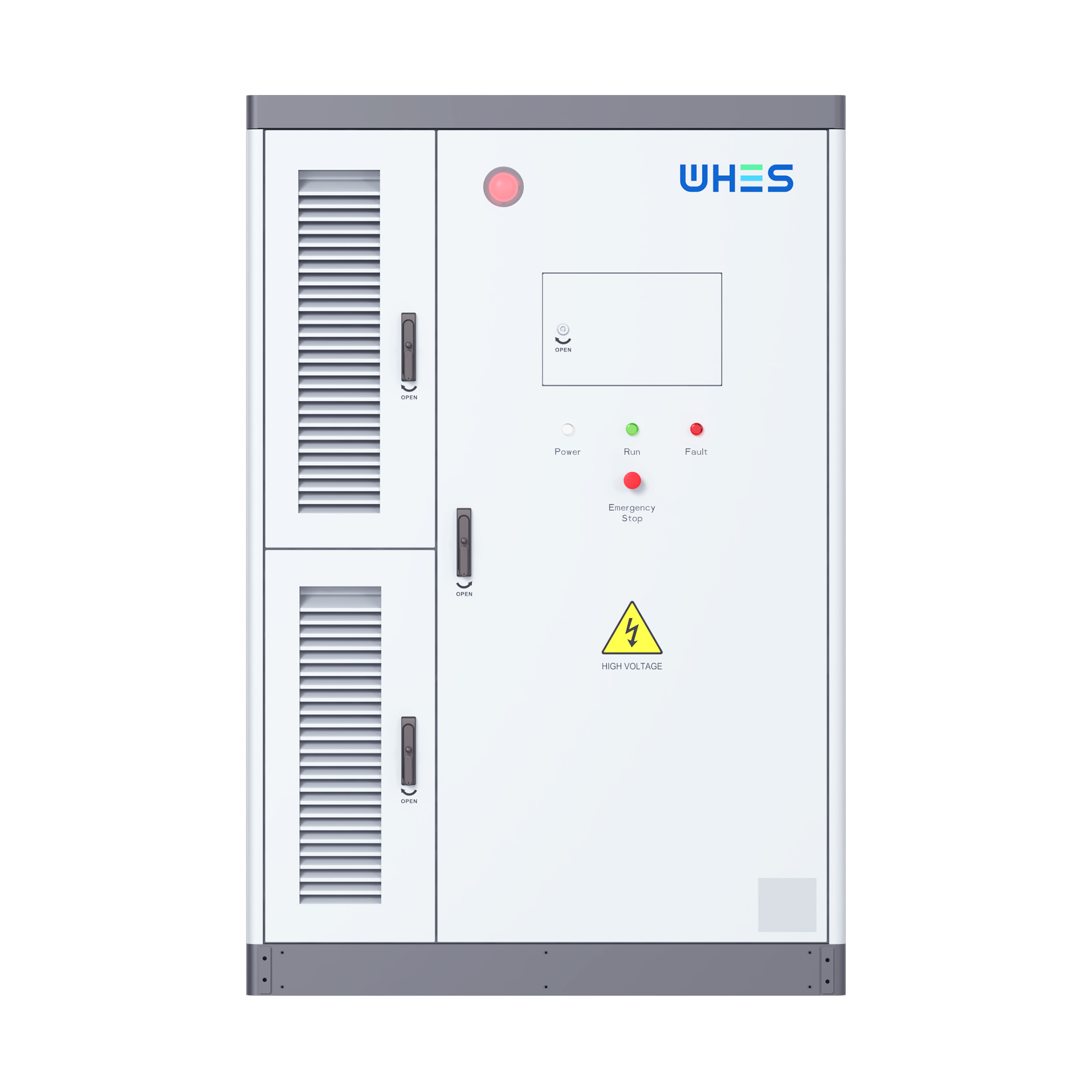
Turnkey solutions reduce integration risk by combining cells, BMS, inverter, and enclosure engineering into a single, factory-tested unit. These systems simplify procurement and speed commissioning, especially when you need standardised answers for warranty and service. If you are specifying multiple sites with similar duty cycles, a validated commercial approach — such as some modern commercial solar battery storage systems — can lower total installed cost through repeatability while preserving the essential metrics you require.
Common mistakes during operation — and practical mitigations
Operators often under-monitor thermal trends or allow SoC windows to drift, which accelerates aging. Implement routine thermal imaging during maintenance, schedule firmware updates for the BMS, and define conservative SoC limits for summer operations. — Periodic field audits of performance against the original acceptance tests help catch drift before it becomes failure.
Advisory: three golden evaluation metrics
1) Net delivered energy per year (kWh/year) under your duty cycle. This collapses RTE, DoD, and degradation into an operational metric you can budget. 2) Guaranteed derating curve and thermal cut-off points. If the supplier cannot show measured derate behaviour, treat the claim as incomplete. 3) Verified interoperability and acceptance test reports with your inverter and EMS — commissioning is where designs become reality, so demand evidence.
For projects that require both predictable performance and reduced integration risk, such validated, factory-integrated systems from reputable suppliers are often the sensible choice — naturally aligning engineering objectives with operational certainty. WHES.
Measured.